Showing all 3 results
-

Custom 3D Name Patch for T-Shirts
Sale! Original price was: ₹599.00.₹499.00Current price is: ₹499.00. Add to cart -

ExaCube – Modular Arduino/ESP32/Pi Pico Enclosure Kit
Sale! Original price was: ₹1,500.00.₹1,000.00Current price is: ₹1,000.00. Add to cart -

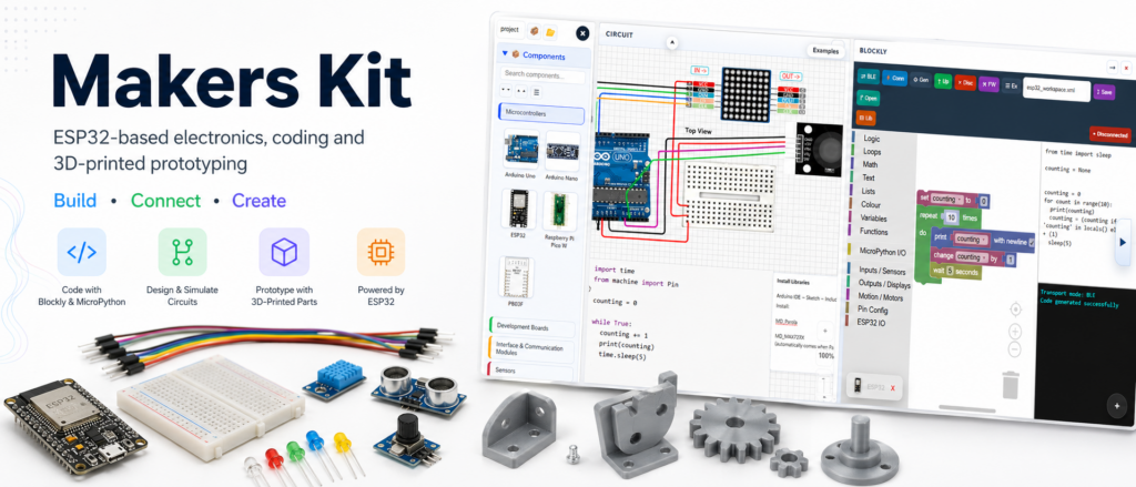
Makers Kit
₹2,999.00 Add to cart
Showing all 3 results